How It Works
Continuous Injection
Continuous injection is the most common method of gas lift. High pressure gas is injected continuously down the annulus, through a gas lift valve, and into the tubing, creating a lightened fluid gradient, reduction of wellbore pressure on the formation, which results in drawdown between the wellbore and formation. This drawdown allows the formation to produce desired fluids.
Intermittent Injection
Intermittent injection is a method of gas lift (typically combined with plunger lift ALS) where gas is intermittently injected, allowing the formation to build pressure while injection is diverted to another well or circulated. Fluids build up in the tubing, well bore pressure builds, and a diversion of gas back to the well lifts the fluid slug to surface. The well is shut-in and process is then repeated.
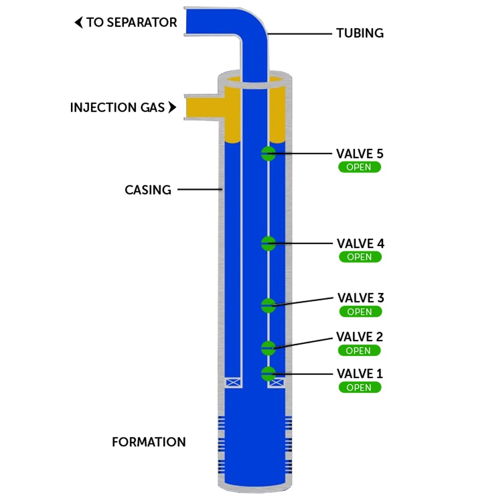 Step 1
After a well has been completed/worked over, in the case of a new well fluid is most often at or near the surface in both the casing and tubing. Due to the hydrostatic pressure of wellbore fluids often times it is too much for the formation to produce hydrocarbons. When gas lift valves are installed, the combination of hydrostatic pressure in the casing and tubing is enough to overcome the opening pressure of all downhole valves. When high pressure gas is injected down the annulus, the fluid in the annulus is pushed through the top valves until the top valve (valve #5) is uncovered.
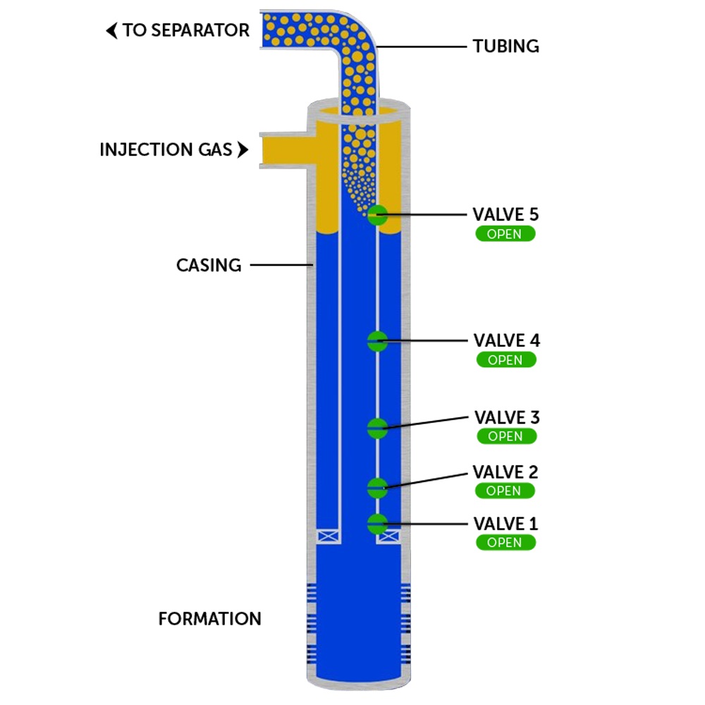 Step 2
Once valve #5 has been uncovered, injection gas u-tubes into the tubing through that valve, lightens the fluid gradient, and lifts fluid to the surface. While gas is flowing through valve #5, fluid is continuing to be pushed through valve #4 (if tubing pressure permits.)
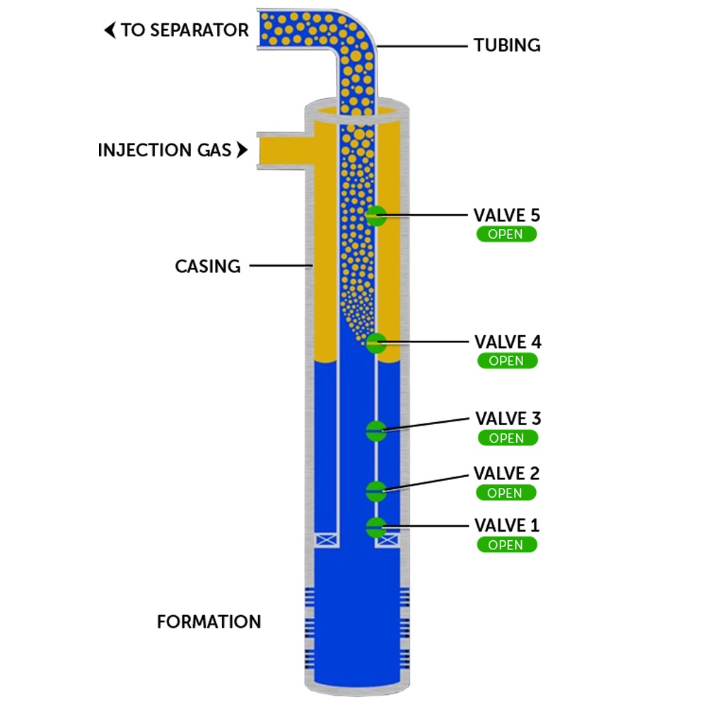 Step 3
Tubing pressure has dropped enough to allow fluid to flow through valve #4 to the point where gas injection has been obtained. Injection gas is shared between valve #4 and #5 briefly while casing pressure begins to drop due to the increase in flow area shared between the two top valves.
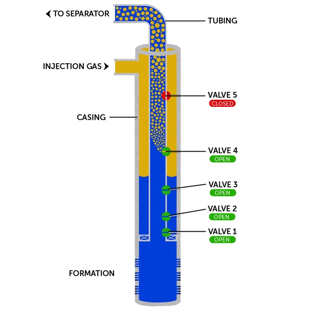 Step 4
Casing pressure has now dropped enough to fall below the closing pressure of valve #5, closing it off and terminating the communication between the casing and tubing. Valve #4 is now the single point of gas injection. All lower valves still remain open due to the combination of hydrostatic pressure and injection pressure.
 Step 5
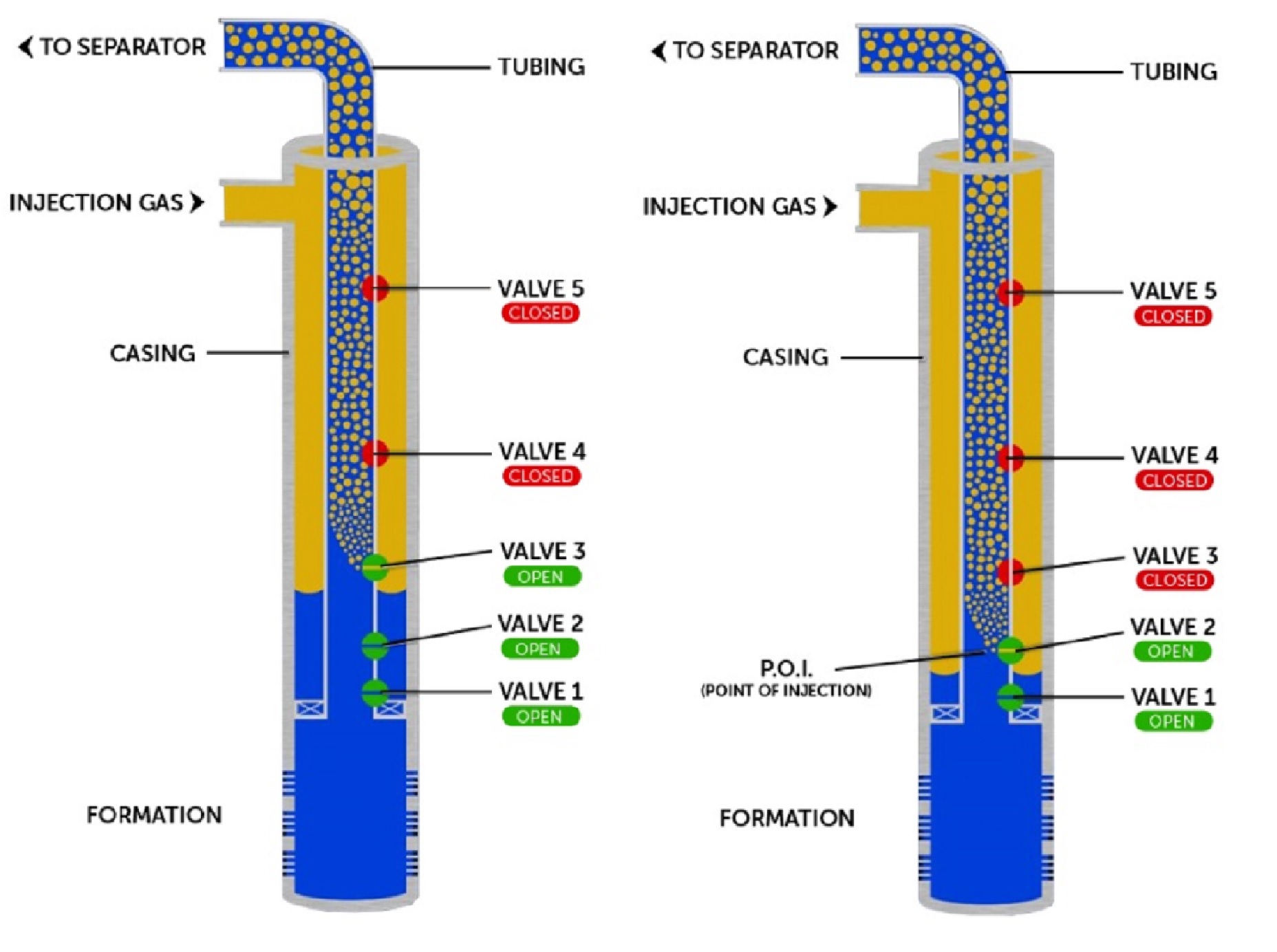
Valve #3 has now been uncovered, and the process will continue until the deepest point of injection is obtained. In the figure on the right, the deepest point of injection is valve #2 which we call the 'operating valve.' Valve #1 is at a depth/pressure situation where Tp>Cp resulting in the check valve being in a closed position. Valve #1 is open due to the combination of hydrostatic pressure and injection pressure, but injection gas is not able to pass due to the sealed check. Once well conditions change enough such that TP is less than CP, fluid will begin and continue to unload from the backside and gas injection through the deepest point possible (valve #1) will be obtained. Flow rate increases may force the operating valve to 'check off', preventing injection gas from entering the tubing at that depth resulting in a casing pressure increase. As casing pressure increases, upper valves begin to open.